Lock-on cameras in Cinemachine
typically mean cameras with components Framing Transposer
and Composer. Cameras with these two components follow the
protagonist while looking at another object, just like when you are
fighting with a BOSS. However, in certain situations the camera will
keep rotating around the protagonist and the look-at object, creating a
very unnatural artifact for the player. This blog post explores how this
phenomenon happens and how to remedy it.
What happens to lock-on cameras in Cinemachine
Lock-on cameras (the combination of the
Framing Transposer and Composer components) in
Cinemachine suffer from severe infinite rotation around the follow
target and look-at target under particular camera settings and when the
two targets are close to each other. We will first briefly explain why
this happens.
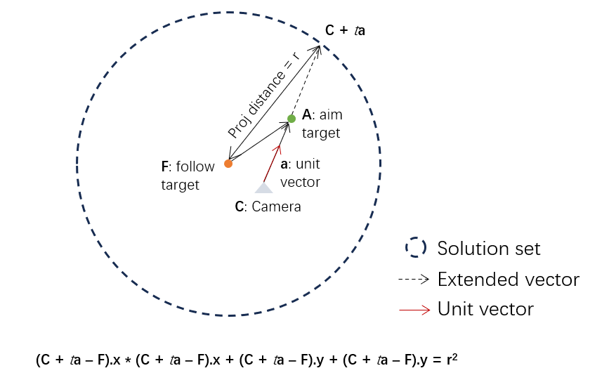
Considering a sphere centered at the follow target position
Derivation of
Assuming the look-at position is
where
which reduces to
This gives us three equations. By substitutions, we have:
However, the problem here is the left hand side

Remedy #1: restricting the Screen X/Y parameter
The first remedy is quite intuitive: we concurrently shrink
where
This technique is simple and effective in reducing the chance of
infinite rotation by cameras, but creates a weird effect that the follow
target will gradually arrive at the center of screen. You can tweak
Remedy #2: pushing away the look-at object
Analysis
Now that this problem is caused by camera's sensitivity to the
projected distance
- The distance between the follow target and the fake
aim target has a minimum value, denoted by radius
. - The camera now looks at the fake aim target and maintains the same orientation as the real aim target.
The second condition implies that the aim target should be extended
along the direction from the camera to the aim target. Based on the the
above equations, it is the direction of the camera forward, i.e.,
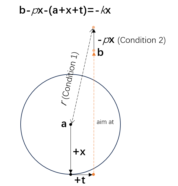
But both conditions cannot be satisfied simultaneously. Let's assume
term
With the the stretched aim target
Rearranging this equation gives us:
The only difference is the coefficient, i.e., from
We must relax one of the two conditions. As we would like to keep a minimum projected distance between the follow target and the aim target, we can relax the second condition, allowing the aim target to show at a different screen position by dynamically adding an offset to the aim target. Then, the real aimed position is the point being offset from the original aim target.
Method
So what is the offset
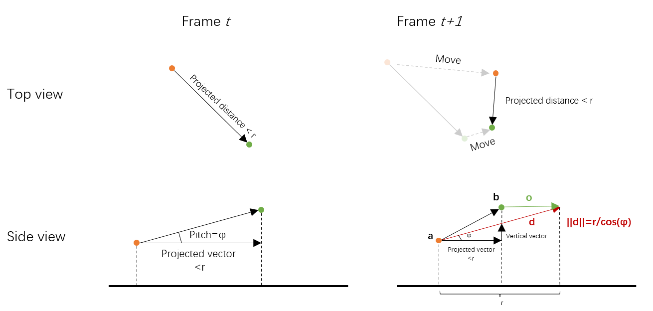
The above figure shows how to keep the so-called static relationship.
In frame
Question: why do we maintain a static pitch angle? This is of course not definite, but a static pitch angle circumvents the problem of camera jitters caused by drastic pitch change.
The following pseudo code shows the process (called in each frame):
1 | Vector3 FollowPosition = GetFollowTarget().Position; |
The code snippet is quite simple and neat. It follows several steps:
- If in current frame the follow target steps into the range of radius
, then cache the pitch . - For each frame where the original projected distance is less than
: - Project the original directional vector
FollowToAim. - Get the vertical vector
Verticalusing. - Get the calibrated directional vector by adding the projected vector and the vertical vector.
- Normalize the directional vector.
- Multiply it by the length
. This gives us . - The offset vector
.
- Project the original directional vector
The following figure shows how this method does to remedy the problem. As the follow target enters the range of radius, the aim target begins to be offset. Seems good so far.
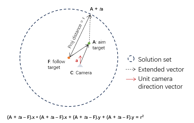
Improvement: blending with another aim target offset
If we only consider the first condition, i.e., the projected distance
is equal to a fixed value
Recall that at the beginning of this section, we analyzed that extending the aim position along the direction of camera-to-aim will not change the aim target's position on screen. This is a nice property because what we exactly want to preserve is the screen space position.
We use the above figure to illustrate how to compute this offset. Let
This is a quadratic function so we can readily solve it. But be careful when this equation is unsolvable.
Pseudo code to compute this offset is shown as follows:
1 | Vector3 FollowToCam = GetCamera().Position - GetFollowTarget().Position; |
Note that using the above calculation, the linearly blended vector
may not maintain a length of
As shown in the figure, we can see the blended offset combines well
both worlds: to keep a fixed screen position and to avoid infinite
rotation when the projected distance is small. The parameter
strength should be chosen differently under different
situations. Generally, a value between 0.5~0.8 performs well.
Camera's forward as offset direction
We can also apply another type of offset to bias the aim target position on screen, that is, the camera's forward direction projected onto the XY plane, shown in the following figure.
Different from the previous case, this time we offset the aim target
along the direction of camera's forward vector (projected onto the XY
plane), denoted by
We can use the same technique to solve this equation. Pseudo code is given as follows:
1 | FVector CamDir = UKismetMathLibrary::ProjectVectorOnToPlane(GetOwningActor()->GetActorForwardVector(), FVector(0, 0, 1)); |
Intuitively, this offset encourages the aim target to maintain its screen space position while constraining the camera's pitch because the real aim position is now horizontally farther and the camera does not need to raise its head to orient to it. This is a trade-off between screen space position and camera's pitch angle, and can be combined with the other two methods.
Using only this offset, we see that the aim target preserves well its screen space position. But the cost is an increased time delay for the camera to lock on the aim target. Interpolating it with the first offset, this artifact disappears.
Summary
In this post, three methods to remedy the infinite rotation issue are proposed, where each has its merits and defects.
- Pitch Offset: This offset is applied to the aim target so that the real aim position and the follow target forms a fixed pitch angle. It will never cause infinite rotation but the aim target will be biased on screen space.
- Camera-to-Aim Offset: This offset is applied in the direction from camera to the aim target and still cause infinite rotation. It is used to pull back the other two offsets so that the aim target manages to maintain at the correct screen space position.
- Camera Forward Offset: This offset is applied along the projected camera's forward direction. As this offset is parallel to the XZ plane, it will not cause the infinite rotation problem is appropriately set. It will not change the aim target's screen position but may increase the delay when the camera looks at the aim target.
In practice, it's recommended to interpolate these three methods to achieve a more natural and smooth result.